Making a PCB board
Written on August 23rd , 2023 by Laura Weller
The general steps
These are the general steps you need to follow to cut a pcf board. Basically to create a board, you need to cut the traces of your PCB. The PCB is the copper plate on which you can solder a chip. To make the board that I created (see image below) you can look on this website (http://academy.cba.mit.edu/classes/embedded_programming/)[http://academy.cba.mit.edu/classes/embedded_programming/]. On the website you will see a list of different boards. Find the one that is called D11C-blink. Then you can download the traces and the interior. When milling these two images make sure you first mill the traces, then the interior (cause the interioir is the outline and if you drill that first the board is not secured on one place hence you don’t have a origin point anymore when you start milling the traces). Now walk through the steps below and you end up with your own pcb board!
1. Designing your board
- To design your electronics, use kicat. You always design an outline and the traces of your PCB.
- When designing your board in kicat and you save your design, your design will be saved with a dpi90. When importing in illustrator, your dpi changes to 72. Make sure you keep an eye on your measurements so you won’t mess up your design. The design that I used in these steps came from (http://academy.cba.mit.edu/classes/embedded_programming/)[http://academy.cba.mit.edu/classes/embedded_programming/] and is called ATSAM D11C-blink. See the images below for the design:
2. Machine
- Deattach the whole door from the machine, turn on the light switch on the right side
- On the machine you have 4 options: the on/off switch, the view position (when clicking this you bring the bit to the home position: upper left position, board moves to the back), the up and down tool (this moves the bit up and down)
- Press the on button, let the machine get into it’s postition. Then press the view button.
- Take a milling bit from the left side - you have different measurements, choose the one you need. Use the milling bits with care, they are quite expensive. In this step by step guide I first milled the traces and then the outline. This means that you first take a milling bit of .4 mm or .2 mm. After that you change the milling bit to .8 or 1 mm.
- Now you make sure that you switch the milling bit in the machine to a .4 or .2 milling bit. This you do by using the hexkey. (see image below). On the head there are 2 inputs, make sure you use the one with the black stickers closest to it.
3. Changing the milling bit
- move the milling bit up with the machine buttons until you clearly see imperial written
- Change via the screw with the red circle. hold the bit with 2 fingers and unscrew the screw (not fully just a little untill the it gets loose)
- Now you push the new bit in as much as you can and you tighten it again with the screw
- Now move the bit all the way down and then up a little (5 mm).
- Now you hold the milling bit and unscrew the screw again, do this gently! Otherwise you will destroy the milling bit. When the end of the milling bit is on the copper, you can screw it tight again. By doing this you are manually fixing the Z-axis of the machine. You can wiggle/turn and tiwst the bit a littlebit to make sure that the z axis is correct (see image above)
4. Computer
- First you need to open the programm you are using.
- Start the computer and look for a mouse
- Go to the computer (when autenticator thing pops up, click 3x cancel)
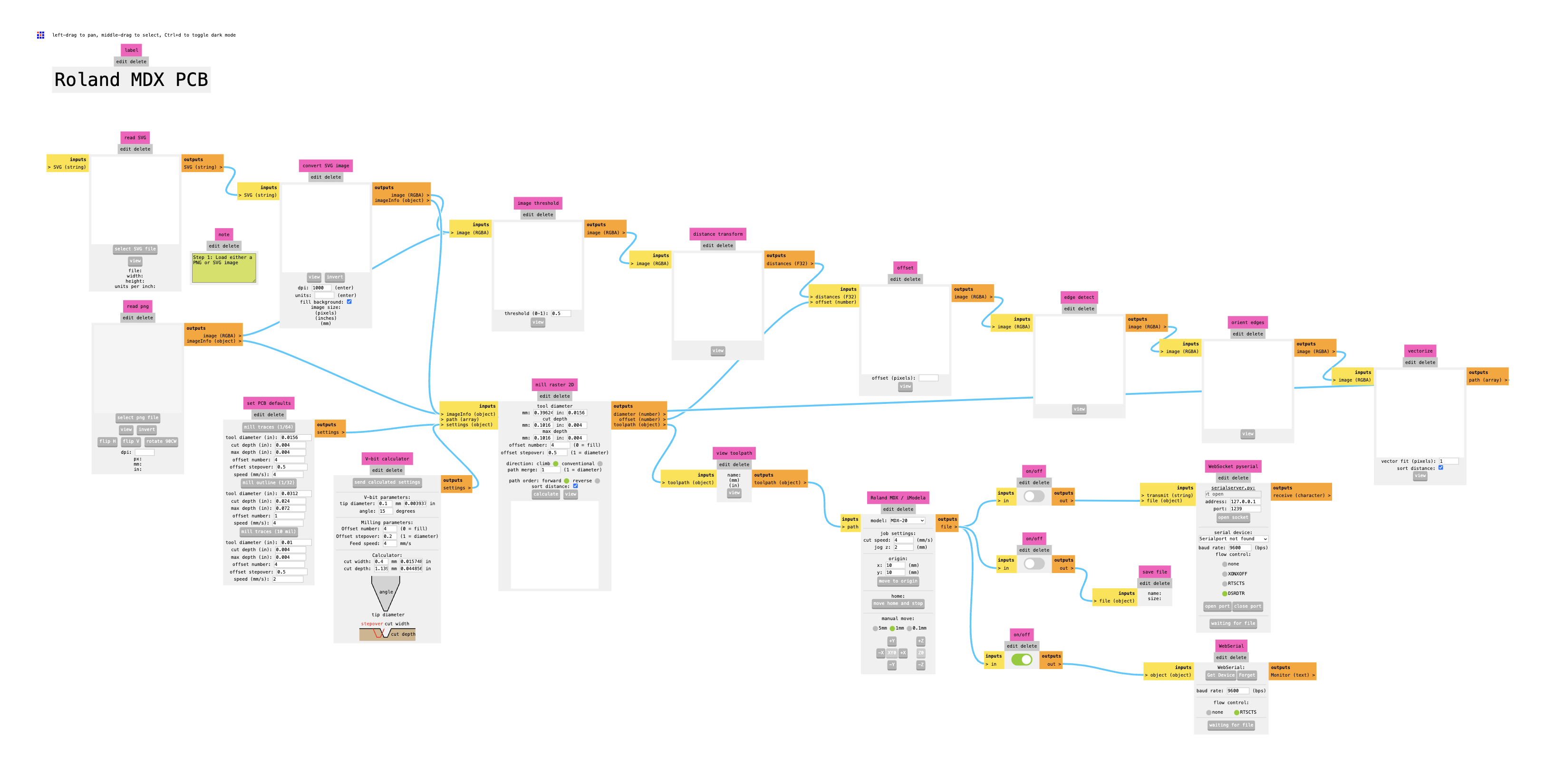
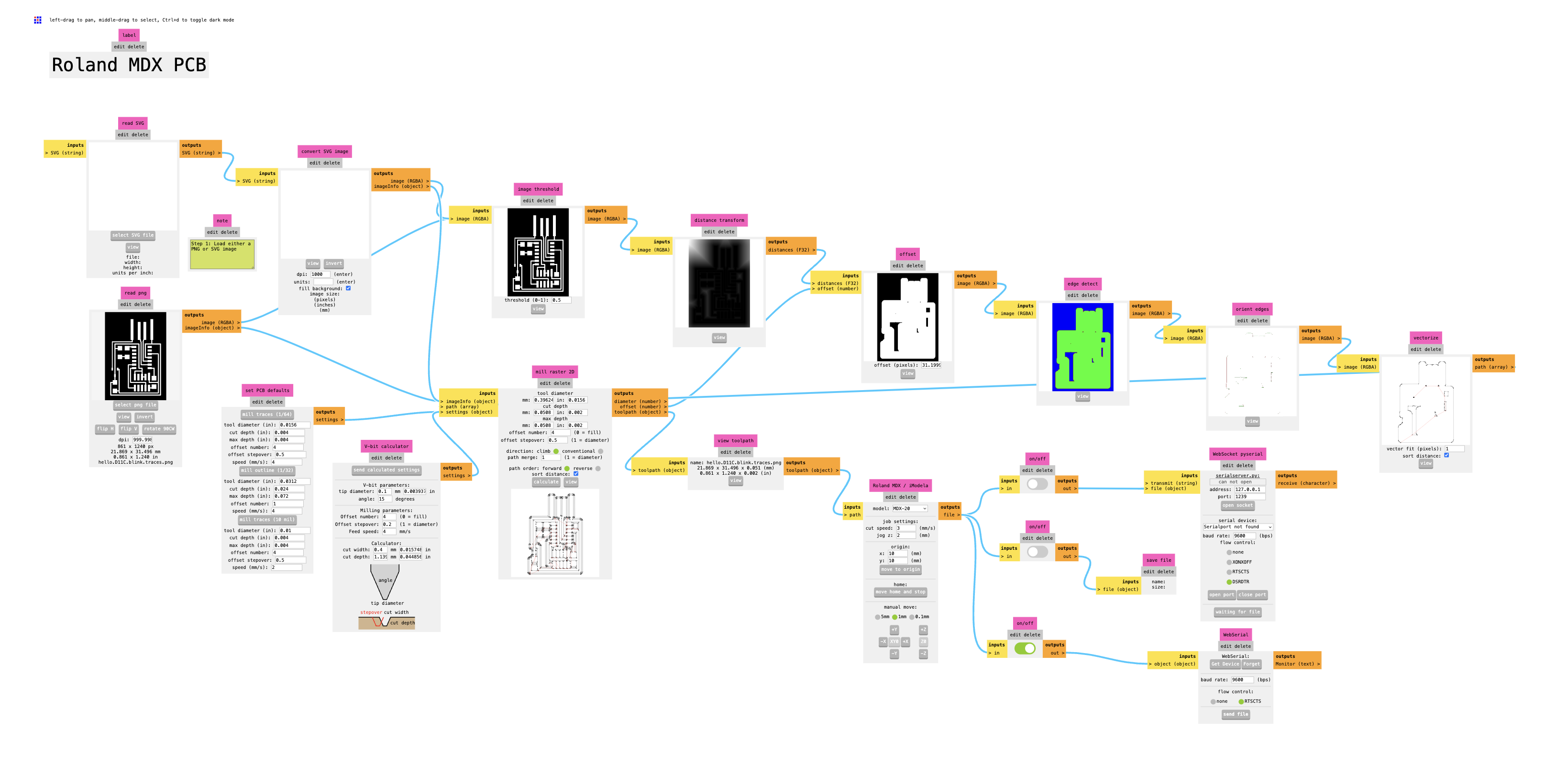
- Go to modsproject.org while using chrome > right click > programms > open programm > you see all kinds of premade options for machines > choose Roland MDX mill PCB > Then all kinds of modules appear > these modules can convert PNG images into something the machine can mill > You read the module from left to right.
- Now you need to specify in the programm what you want to mill.
- So we start at the left READ SVG/READ SVG > select PNG file (or SVG file) > Now you can select the image you created or the image you downloaded (the traces or interior image). When the image selected you see the design
- Check if the dpi is on 5000
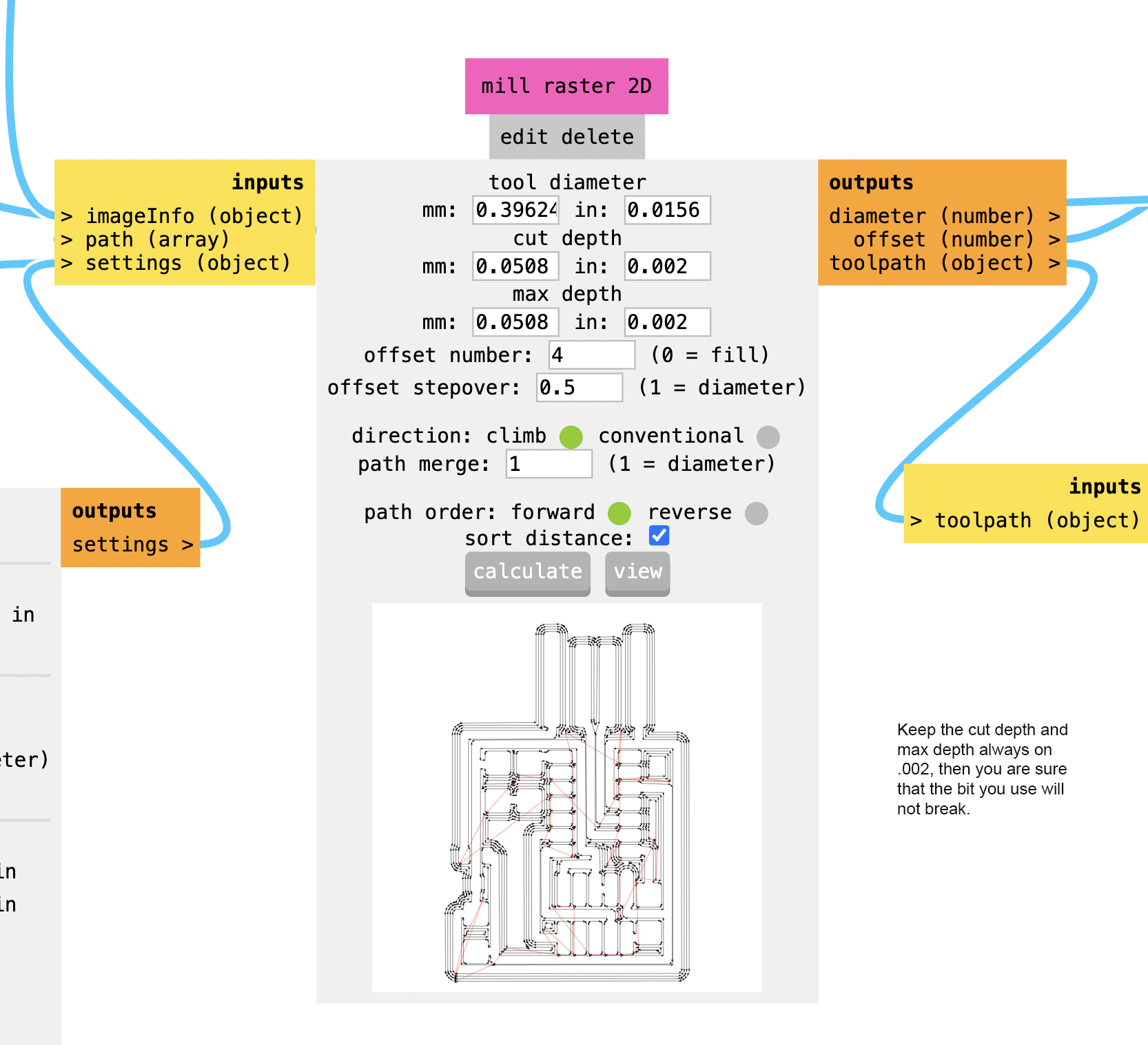
- Specify how deep and how fast you want to cut. This you do by going to mill all traces > mill raster 2D > tool diameter > write the right size of your bit > cut dept > always around 0.002 inch > Max dept > is the same as the cut dept (unless you are cutting multiple layers) > offset number 4 > offset stepover 0.5 or 1 > directon clim > path merge 1 > Now press calculate
- This step is a bit different for milling traces and milling the interior. If you mill the traces, a cut depth and max depth of 0.002 is often enough. If you mill the interior, you need to cut through the copper plate. Therefore you need to measure the thickness of the copper plate. Depeding on how thick the plate is (ours was 1.55 mm, so we set it on 1.6 mm - a bit moe to calculate the plastic tape that lays underneath with it as well) you change the max depth in 1.55 mm while leaving the cut depth on 0.002 inch (or a bit more since the bit is thicker and therefore stonger (0.003 inch is also an option)).
- So we start at the left READ SVG/READ SVG > select PNG file (or SVG file) > Now you can select the image you created or the image you downloaded (the traces or interior image). When the image selected you see the design
- Now you need to connect the computer with the machine.
- This you do by going to webserial > get device (rightbottom on the modsproject screen) > you get a pop up to connect to a serial port > scroll down > usb serial controller D > connect
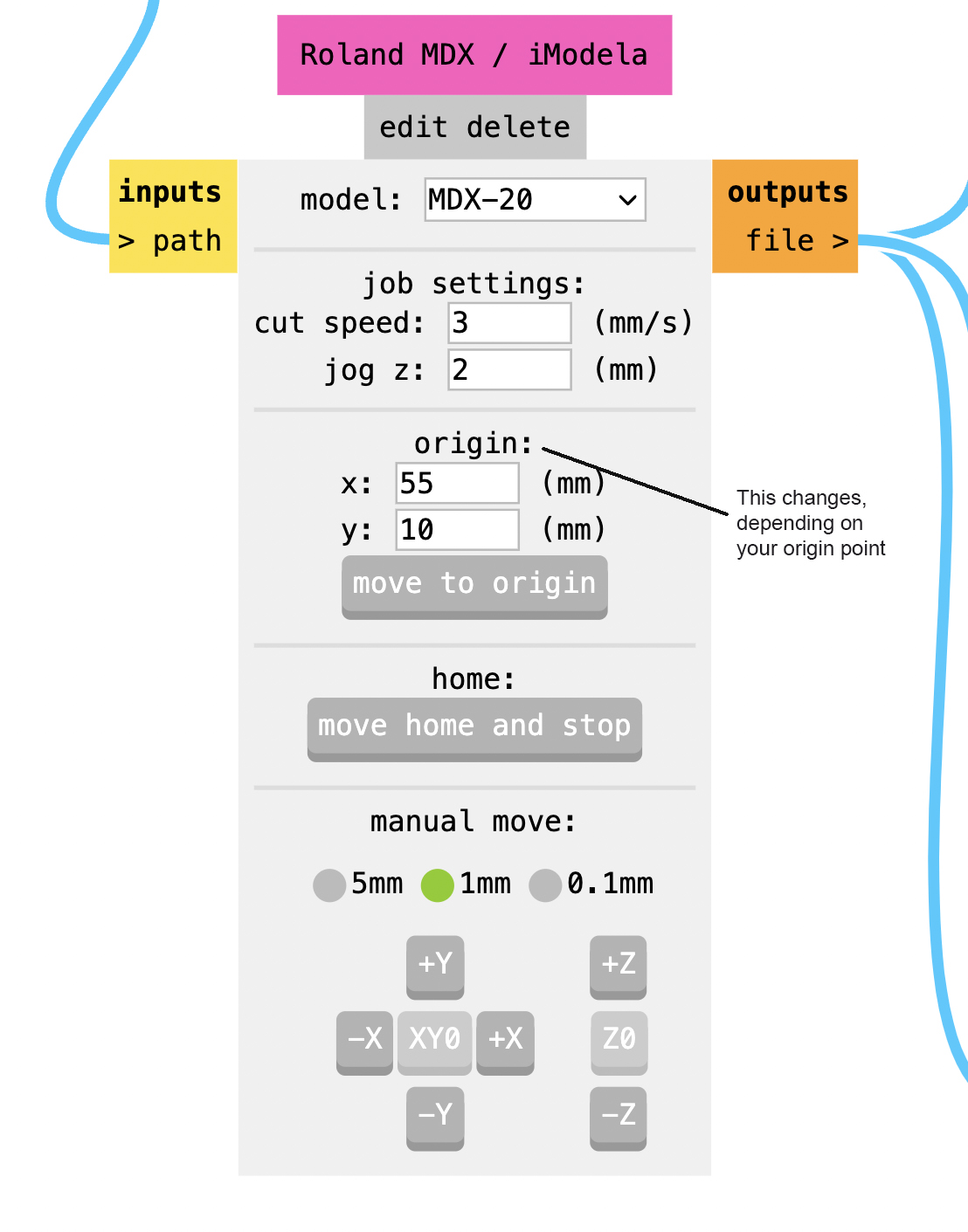
- At the Roland MDX frame you can change the x and y values of the machine
- Go to the machine. You are in home position > you need to point 0 on the X & Y axes > press view > click on computer: move to viewpoint > move to the bottom left of where you want to start your design. You can do this by changing the x and y axes in the Moland MDX/ umbrella on your computer> now you can lower the bit. Don’t use the -z and +z axes on the computer, but use the ones on the machine
- Make sure to put the cut speed on 3 and the jog z on 2
- Once you’ve found a spot that you are content with, you can lower the milling bit onto the copper plate. This you do by bringing the bit down on the z axis untill the machine can’t go any further by pressing the down button on the machine. At some point the bit won’t go lower. Now bring it up just a little (so it can mill, otherwise it wont go depper then the surface of your copper plate and therefore it won’t mill). Now bring the bit down by hand (as if you are changing the bit). Rub the bit a little between your fingers to really get onto the copper plate surface and screw the hexkey back to keep the bit steady.
- Here you can see images below of before and after I went through steps 2, 3 and 4:
5. The final milling
- press calculate (to make sure that your current settings are connected to the machine)
- go to web serial > send file
- Now put back the cover over the machine to minimize noise. If you see dusty lines appear, you are doing good!
- When the machine is done, you need to vaccuum away the copper dust (use the vaccuum on the right side)
- Now we need to cut the outline the pcb (on a pcb you can solder a chip). For cutting the outline you always use .8 or 1 mm its. For cutting the traces, this depends, I recommend using .4 mm. This meant we need to change the bit again from .4 mm to .8 or 1 mm.
- Now you select the png file of the outline
- SET PCB defaults > mill outline > ill raster 3D > change the bit size > cut depth 0.6 > max depth 1,7 mm > now it will cut the ouline in 3 times (.6, .6 and .5). By doing this you won’t murder the bit (cutting 1,7 mm depth in one go with a .8 milling bit is not gonna make the milling bit last). Make sure then when cutting the outline your max depth is 1 mm less then the actual dept of your copper board.
- press calculate > when everything is correct again you press send file
- When you have cutted the traces and the outline, you take out the bed with a flat screwdriver
- If it wiggles a littlebit, you can take it out and it is cutted correctly.
6. General notes
- Note: if you export from kicat to illustrator, you need to put the BPI - 72
- To pause always press view
- If it does not go through all the way you need it means that you did not put the bit on the board but a little to much upward. FOr this you need to hold up & down at the same time until the blue light starts blinking. Now you refresh the page on your computer an go through all the steps again.
7. If the milling bit is broken
- Pause the machine (press view).
- Save the values of you point of origin (you can find this back in the computer under Moland MDX/ umbrella)
- Refresh your page on the computer
- Press the up and down button together for a few seconds (the lights will start blinking)
- Connect the machine to the computer again (step computer 3)
- Bring the machine back to origin point (by filling this in on Moland MDX/ umbrella)
- change the milling bit to one that isn’t broken
- Upload the image and specify how you want to mill (step computer 2)
- start milling (step The final milling)
- The machine will first mill the pathways that the old bit has already milled and continue where the old bit got broken. Here you will see more dust apprearing. That is a good sign.
8. Solder you pcb board
- Now that you have milled your pcb board, you need to solder the right things onto it. This you do by going back to (http://academy.cba.mit.edu/classes/embedded_programming/)[http://academy.cba.mit.edu/classes/embedded_programming/]. Here you look at the pcb board that you have downloaded (in our case D11C-blink). You download the board and components of the design. Here you see all the information of the things that need to be soldered onto the pcb board. You can find them in the little drawers on the wall (see image).

After soldering, you have a result like this. See the before and after soldering images below:

9. Activating your soldered pcb board
- Now you need to make sure that your baord is flashed (in order for the computer to find it once you plug it in). Flashing you do through Arduino (a coding programm). Download arduino on (https://www.arduino.cc/en/software)[https://www.arduino.cc/en/software].
- Open the Preferences of the Arduino IDE.
- Add this URL https://www.mattairtech.com/software/arduino/beta/package_MattairTech_index.json in the Additional Boards Manager URLs field, and click OK.
- Open the Boards Manager (menu Tools->Board->Board Manager…)
-
Install MattairTech SAM D L C Core for Arduino - Beta build -
Select one of the boards under MattairTech SAM D L C Core for Arduino in Tools->Board menu (for this board it’s the D11C14). - Open the Preferences of the Arduino IDE again
- Add this URL https://raw.githubusercontent.com/qbolsee/ArduinoCore-fab-sam/master/json/package_Fab_SAM_index.json in the Additional Boards Manager URLs field, and click OK.
- Open the Boards Manager (menu Tools->Board->Board Manager…)
- Install Fab SAM core for Arduino - Beta build
- Now you need to use an older, already flashed, pcb board to flash your one. This you do by putting both in a usb plug (putting paper underneath it helps the usb plug to read it - make sure you don’t use the plugs of your computer but an expternal one since the process might ruin your usb port and you rather have that on an external port that the one in your computer as the one in your computer is expensive and much work to repair). before plugging them in on the usb port they also need to be connected to one another. This is done by connecting the JW SD1 from the one board to the other. Make sure that if you have an JW SD1 with 10 pins, you use an already flashed board with 10 pins (same accounts for 4,6,8 etc. pins).
- Now copy paste the code in Arduino. The code can be found on the same website where I got my design from: (http://academy.cba.mit.edu/classes/embedded_programming/)[http://academy.cba.mit.edu/classes/embedded_programming/]. Now look under blink.ino (in stead of the traces or interior).
- When copy pasted the code you select the right usb-input (see images below), verify and upload.
-
